Digital multimeter circuit diagram pdf
digital ohmmeter Circuit diagram using pic microcontroller Circuit diagram of digital ohmmeter using pic microcontroller is given below. As shown in figure below, resistance R1 is pulled with 5 volt source and resistance whose value we want to measure is …
Use your digital multimeter (DMM) to ensure all power to the circuit is OFF. If the capacitor is used in an ac circuit, set the multimeter to measure ac voltage. This Computer Data Lines Circuit diagram provides the wiring between modules so you are SOLUS Edge w SureTrack 54c175da20eb2 a DMM ohmmeter, such as the Fluke 88V, to determine if there is a short to ground in the data circuit. Fluke
Before measuring current, check the meter’s fuses and turn power off to the circuit before connecting the meter to the circuit. Before rotating the range switch to change functions, disconnect test leads from the circuit under test. Before attempting to insert transistors for testing, always be sure that the test leads have been disconnected from any measurement circuits. Remove test leads
digital multimeter block diagram and explanation Fri, 14 Dec 2018 11:48:00 GMT digital multimeter block diagram and pdf – Electronic Circuit Schematics.
digital multimeter diagram datasheet, cross reference, circuit and application notes in pdf format.
Digital Amp Meter Wiring Diagram Full Online The way to Value Your Digital Amp Meter Wiring Diagram Full Online eBook You’ve written and compiled an Digital Amp Meter Wiring Diagram …
Power/SWR Meter — Circuit Description Figure 3 shows a front panel view of the power meter. I used a two line, 20 charac- Figure 4 shows the schematic diagram and parts list of the power meter…
Related Book PDF Book Digital Amp Meter Wiring Diagram : – Fuse Box 2001 Volvo V4 0 – Free Bmw Wiring Diagrams – Fuse Box Bmw 1 Series – Fpv 250 Wiring Diagram
Fluke Multimeter circuit diagram datasheet, cross reference, circuit and application notes in pdf format.
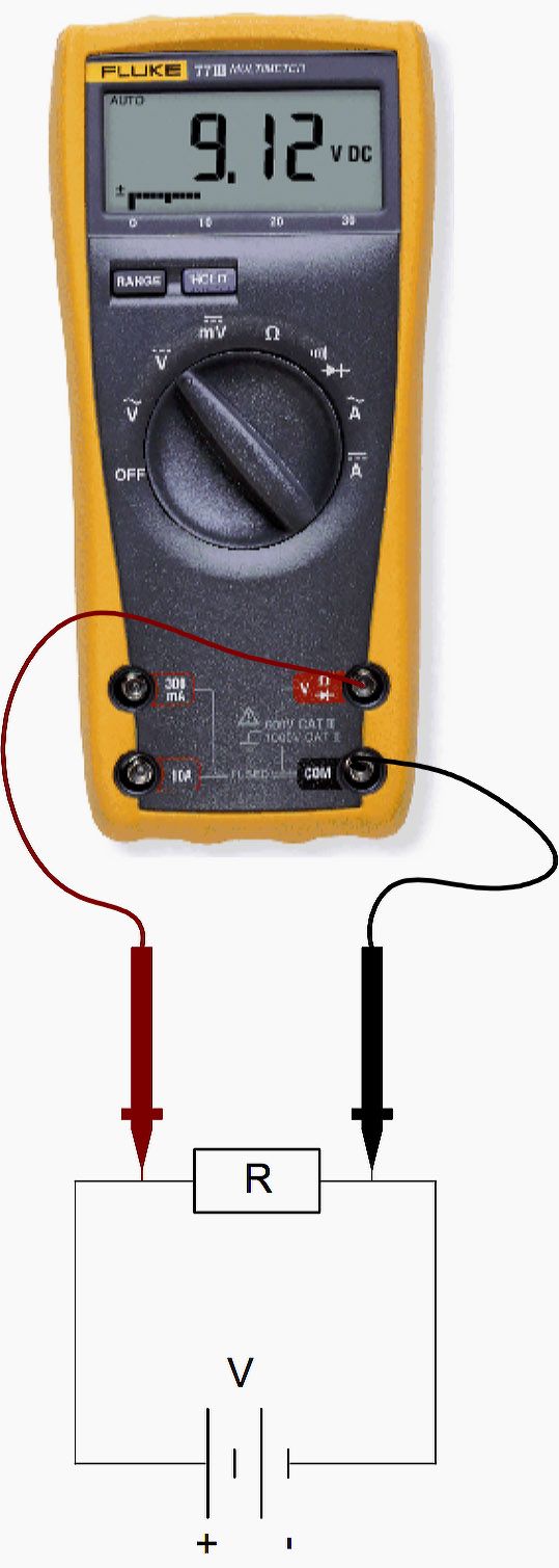
Measure Current through R 1, I R1 3 Ω 3 Ω 5 Ω 5.0V You can place the meter on either side of the resistor. Notice the polarity of the meter leads are opposite
16/10/2015 · The opposite is true.I had been trying before to find that circuit diagram in the web by myself but with no success,thinking it might help me to solve the problem. But since i didn’t know what might cause the DMM behavior,i didn’t know from where to begin with.
Digital Amp Meter Wiring Diagram

Make Your Own Multimeter DC Circuits All About Circuits
22/09/2014 · I recently purchased a DT-830B digital multimeter, something like this The DT830B pocket-size digital multimeter, from ebay. The item arrived early and the packaging seems intact.
off to the circuit before connecting the meter to the circuit. Before rotating the range switch to change functions, disconnect test leads from the circuit under test. 3 Before attempting to insert transistors for testing, always be sure that the test leads have been disconnected from any measurement circuits. Remove test leads from the meter before opening the Meter case. MAINTENANCE Before
Circuit diagram. Compass. Earth’s magnetic field. Electronic color code. Multimeter. Right-hand rule. Solenoid. Multimeter . A digital multimeter . A multimeter or a multitester, also known as a volt/ohm meter or VOM, is an electronic measuring instrument that combines several measurement functions in one unit. A typical multimeter may include features such as the ability to measure voltage
Scouting for Digital Amp Meter Wiring Diagram Full Download Do you really need this pdf of Digital Amp Meter Wiring Diagram Full Download It takes me 39 hours just to acquire the right download link, and another 4 hours to validate it.
Appendix C: Building Snap-Circuits ® Use myDAQ digital multi-meter (DMM) to test MySnap components if they appear to be damaged or not working properly. 7. Use eye protection when experimenting on your own circuits. 8. Always remove power if circuit does not perform properly, and then use myDAQ DMM to check circuit for shorts or opens. WARNING: SHOCK HAZARD Never …
The circuit works like many other digital measurement circuits in that it converts the quantity to be measured into a time interval, then measures that time. Call the voltage we wish to measure V in .
To do this, disconnect all components from the previous testing circuit and connect your digital ohmmeter across the meter movement terminals. Record this resistance figure along with the full-scale current figure obtained in the last procedure.

Circuit Diagram Of Digital Multimeter Figure 8 shows the DMM voltage levels and the circuit diagram of this audible accessory. The 79L05 negative voltage regulator derives a potential 5 V below.
Multimeter will be used in several labs, and important for checking circuit when doing your final project . Digital multimeters will be provided by the lab. A check out form must be approved and signed by a TA
meter is connected to the circuit to be measured. 1.2.4 Keep your fingers behind the probe barriers when taking a measurement with an effective voltage above
Free Download ==>> Digital Amp Meter Wiring Diagram
Fluke Digital Multimeters. Circuit Specialists carries affordable Fluke benchtop & handheld digital multimeters, The handheld units retain many of the features and much of the power of their professional-grade benchtop multimeters — so you get power and portability without breaking the bank.
Description. The circuit given here is of a very useful and accurate digital voltmeter with LED display using the ICL7107 from Intersil. The ICL7107 is a high performance, low power, 3.5 digit analog to digital …
Our integrated circuits and reference designs help you design low cost, low power, and high performing digital multimeter products capable of 4.5 to 8.5 digits of resolution. Modern digital multimeters …
worth on the low side. Some authors have even priced their ebooks at a profit loss to draw a high number of new customers. The hot button is to find a value that maximizes your earnings
Digital Multimeter Circuit Of Digital Multimeter. schematic diagram power saver device, schematic diagram dt9205a digital multimeter, wiring diagram for 30 amp relay, circuit diagram … – digital revolution timeline books pdf Cen Tech Digital Multimeter Manual 98025 PDF file for free, Get many PDF Ebooks from our online MANUAL DE. USUARIO DT9205A MULTMETRO DIGITAL. —Digital multimeter, voltage, current, resistance and capacitance can be tested, continuity The device employs advanced power control and protection circuit. The Excel DT9205A is a single chip meter possibly based on a variant of the …
The voltmeter is based on single ICL7107 chip and may be fitted on a small 3cm x 7cm printed circuit board. The circuit should be supplied with a 5V voltage supply and consumes only around 25mA. The circuit should be supplied with a 5V voltage supply and consumes only around 25mA.
Related Book Ebook Pdf Digital Meter Wiring Diagrams : – Dodge Journey Fuse Box Location – Dual Stepper Motor Wiring Diagram – Download Velamma Episodes 7 To 14 Apk
Digital Multimeter Block Diagram And Explanation
Epub Book-]]] Digital Amp Meter Wiring Diagram
Fluke 175 Schematic Diagram WordPress.com
Epub Book-]]] Digital Meter Wiring Diagrams

schematic diagram Dt9205A digital multim Service Manual
[[Epub Download]] Digital Amp Meter Wiring Diagram

Fluke Digital Multimeters circuitspecialists.com
Digital Multimeter Dt9205a Schematic Diagram
–