Congratulations on choosing the Lamona energy‑efficient washing machine. This guide covers safety, installation, operation, and maintenance to ensure optimal performance and protect users from injury or damage. Follow all instructions carefully. Ensure hoses are straight and not kinked to avoid errors
Safety and Warning Information
Use only as intended. Avoid hose kinks behind machine to prevent errors. Beware of electric shock, fire, and serious injury risks. Follow all safety symbols and instructions to protect yourself and property. Keep children away while operating.and keep area clear.
General Safety Precautions
Before using the Lamona washing machine, ensure the appliance is placed on a stable, level surface to prevent vibration or tipping. Keep the surrounding area dry and free of liquids to avoid accidental slips. Do not overload the drum; follow the load capacity indicated in the manual. Keep children and pets away from the machine while it is running. Do not touch moving parts or the door seal during operation. Unplug the unit when not in use or during maintenance. Do not use the appliance for non‑domestic purposes. Keep the machine away from heat sources, flammable materials, and direct sunlight. Store detergent and additives in a cool, dry place, out of reach of children. Follow all local regulations for electrical connections and ensure the power supply matches the machine’s voltage rating. Always read the full instruction manual before first use and keep it for future reference.
The appliance should be inspected for any visible leaks or damage before each use. Keep the door latch and seal clean and dry to ensure a proper seal. Do not place heavy objects on top of the machine while it is running. Avoid using the washing machine for washing hazardous or flammable materials. Ensure the machine is positioned away from direct heat sources and that the surrounding area is well ventilated. Never leave the appliance unattendedduring operation. Additionally, ensure the machine’s drainage hose is securely connected and free from obstructions to avoid leaks and flow.
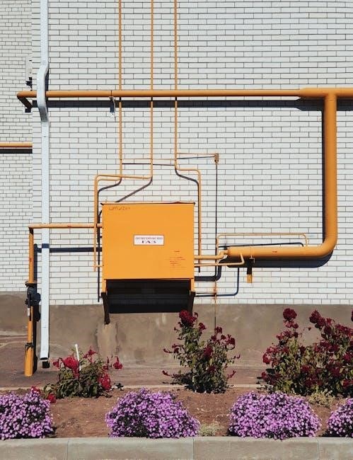
Electrical and Fire Risks
Lamona washing machines are designed for domestic use, yet improper handling can pose serious hazards. The appliance carries explicit warnings for electric shock, fire risk, injury, and death. Ensure the unit is connected to a properly grounded supply and that the mains voltage matches the specification. Do not use damaged cords or adapters; replace any frayed or exposed wiring immediately. Keep the machine away from flammable materials and direct sunlight, and do not expose it to high temperatures or open flames. The installation instructions stress that hoses must not be kinked behind the machine; a kinked hose can cause water leakage, short circuits, or overheating, leading to fire or electric shock. If the machine fails to fill or empty, error codes will flash on the display—check hose integrity and connection. Always keep the user manual in a safe place for reference. Follow all local electrical regulations and use a certified electrician for installation. Never leave the machine unattended while running, and unplug it during maintenance or when not in use. These precautions help prevent electrical faults and fire incidents, ensuring safe operation of your Lamona washing machine. Remember that safety features like automatic cut‑off during overheating and a pressure relief valve protect the machine and user. If a fault occurs, the display shows an error code and the machine pauses until resolved. Consult the manual for troubleshooting or call authorized service. for help at center.!
Installation Guidelines
Follow the supplied instructions. Place the machine on a level surface with proper ventilation. Connect water hoses straight, avoiding kinks behind the unit. Secure the drain hose and attach the power cord to a grounded outlet. Verify all connections before first use!!
Hose Installation and Kinking
Proper hose installation is critical for safe and efficient operation of your Lamona washing machine. The manufacturer’s instructions explicitly state that hoses must be connected without any kinks, especially behind the machine. A kinked hose can restrict water flow, causing the unit to fail to fill or empty, and may trigger error codes or flashing symbols on the display. In addition to operational issues, a kinked hose poses serious safety hazards, including the risk of electric shock, fire, or property damage. The manual warns that improper hose placement can lead to personal injury or death. Therefore, always lay the hoses in a straight line, avoid sharp bends, and secure them with clamps or ties if necessary. After installation, test the machine by running a short cycle to confirm that water enters and exits correctly. If any error codes appear, double‑check hose routing and straighten any bends before retrying. Following these precautions ensures reliable performance and protects you and your household from potential hazards.
Remember that the hose length should not exceed the manufacturer’s recommended maximum to prevent sagging or undue pressure. Use only hoses rated for washing machine use, and replace any hose that shows signs of wear such as cracks, bulges, or leaks. Keep the hose free from debris and ensure the fittings are tightened securely to avoid water spillage. If you notice any unusual noises or vibrations during operation, inspect the hose connections and adjust as needed. Proper hose maintenance extends the life of your appliance and safeguards your home from water damage. Check hoses.
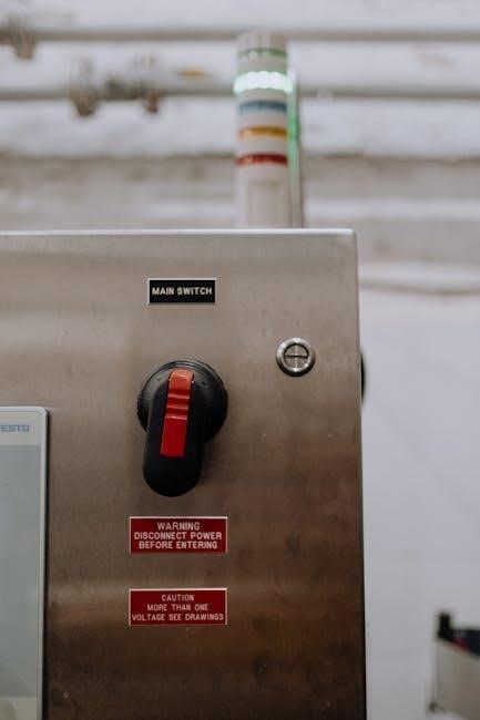
Control Panel Overview
The control panel of the Lamona washing machine is designed for intuitive operation and includes a digital display, selection buttons, and indicator lights. At the top of the panel you will find the main power switch, which must be turned on before any other functions can be accessed. Below the power switch, a series of circular buttons allow you to choose wash programs, adjust water temperature, set spin speed, and add extra rinse cycles. Each button is labeled with a clear icon and a short text description. The central display shows the selected program, remaining time, and error codes during operation. Indicator LEDs are positioned around the display to provide real‑time status updates: green light indicates normal operation, yellow light warns of a minor issue, red light signals a critical fault that requires attention. A blue light indicates low water level. The panel also includes a dedicated button for “delay start,”. For convenience, a “quick wash” button is available for short loads, and a “child lock” feature can be activated to prevent accidental changes to the settings. All buttons are ergonomically spaced and feature tactile feedback, ensuring that even users with limited dexterity can operate the machine safely. The panel’s design complies with local safety regulations and is constructed from durable, high materials to withstand rigors of daily use and is energy efficient. By familiarizing yourself with each element of the control panel, you can maximize the efficiency of your washing machine and troubleshoot any issues promptly.
Wash Programs and Settings
The Lamona washing machine offers a variety of pre‑set programs designed to meet the needs of different fabrics and load sizes. The “Cotton” program is ideal for durable textiles, running at a high temperature with vigorous agitation to remove tough stains. The “Synthetics” program uses a moderate temperature and gentle agitation to protect modern fabrics from damage. The “Delicates” setting features a slow spin and a short wash time, making it perfect for fragile items such as lingerie and silk. The “Heavy Duty” program is engineered for bulky items like blankets and towels, providing a longer wash cycle and higher spin speed to ensure thorough cleaning. For quick, lightly soiled garments, the “Quick Wash” cycle completes in 15 minutes, while the “Rinse” option adds an extra rinse cycle for a more thorough cleanse. The “Spin Only” mode removes excess water before drying, reducing drying time and energy consumption. Users can adjust water temperature (cold, warm, hot) and spin speed (low, medium, high) to suit their preferences. The “Eco” program optimizes water usage and energy efficiency, making it an environmentally friendly choice. Each program is displayed on the digital panel and can be selected with a single button press. The machine automatically adjusts wash duration based on load size, detected by built‑in sensors, ensuring efficient use of water and electricity. If a custom program is required, users can manually combine settings, but the default programs provide the best balance of cleaning performance and energy savings.
Detergent and Additives Usage
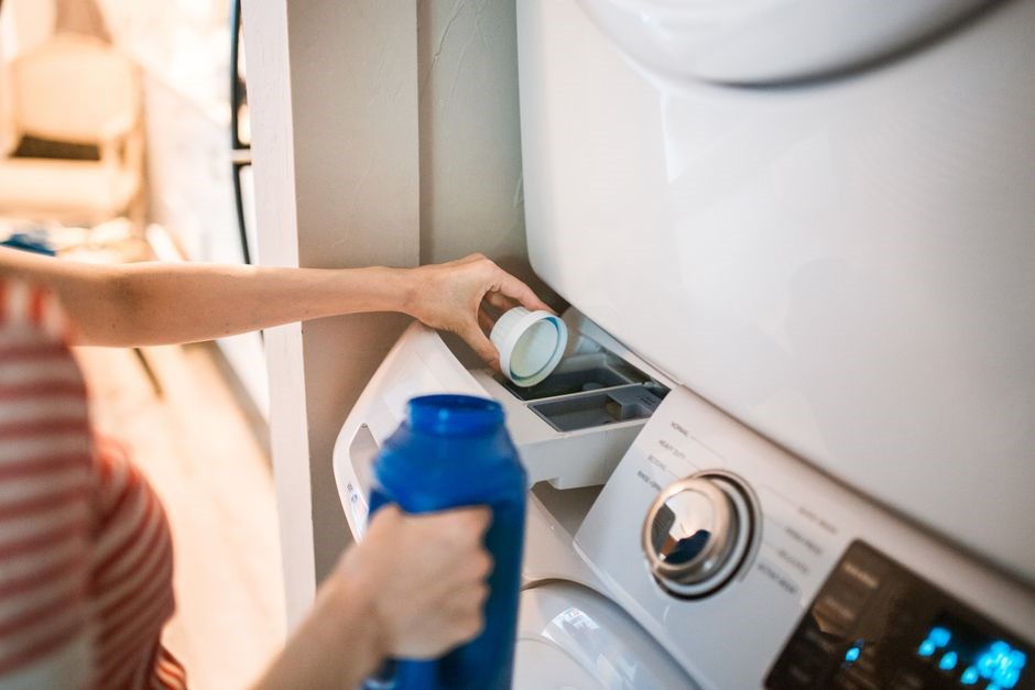
Use the recommended amount of detergent for each load size to avoid residue buildup. For standard loads, a single scoop of liquid detergent or a tablet is sufficient. Heavy‑soiled or large loads may require an extra half scoop to ensure thorough cleaning. Additives such as fabric softener or stain remover should be added to the designated compartments in the detergent drawer. Fabric softener is best used in the rinse cycle to keep clothes supple, while stain remover is applied directly to spots before the wash begins. Avoid over‑loading the machine; excess fabric can prevent proper agitation and water circulation, leading to inadequate cleaning and detergent residue. Always check the detergent drawer for any damaged or clogged compartments before each wash. If the drawer is clogged, clean it with warm water and a soft brush. Use only detergents and additives that are compatible with the machine’s water hardness level. For hard water areas, a water softener additive can improve detergent performance and reduce mineral buildup. Never use powdered detergents in the main wash compartment, as they can clog the filter and cause the machine to display error codes. Instead, use powdered detergent in the pre‑wash compartment if the machine supports it. Keep the detergent drawer dry when not in use to prevent mold growth. Store detergents in a cool, dry place away from direct sunlight. When using liquid detergents, ensure the bottle is tightly sealed to prevent leaks. For eco‑friendly opt
Maintenance and Troubleshooting
Check hoses for kinks; a kinked hose triggers error codes and prevents filling or draining. Keep the detergent drawer clean and dry. If the display flashes or errors appear, verify the machine is level and that no foreign objects block the drain. For persistent issues, consult the user manual or contact support.
Routine Maintenance
Regular upkeep keeps the Lamona washing machine running efficiently and extends its lifespan. Begin each cycle by inspecting the inlet hoses for kinks, cracks or loose fittings; a kinked hose can cause filling or draining errors and should be straightened immediately. Next, clean the detergent drawer after every wash to prevent residue buildup that can clog the dispenser. Wipe the door seal with a damp cloth to remove lint and detergent film, ensuring a tight seal for optimal washing performance. Every month, run a cleaning cycle with a cup of vinegar or a commercial washing‑machine cleaner to dissolve mineral deposits and eliminate odors. Keep the filter, located at the bottom front of the machine, free of lint and debris by removing it with a soft brush or a vacuum attachment. Finally, verify that the machine remains level by adjusting the feet; an unlevel unit can lead to excessive vibration and wear. By following these simple steps, you maintain a clean, efficient, and safe appliance. Additionally, inspect the door gasket for cracks, replace it every 2 years. Check the water inlet filters for clogs and clean them quarterly. Monitor the drain pump for noise; if it sounds like a motor failing, schedule service. Keep the machine in a dry area and avoid overloading. If you notice any leakage around the hoses, tighten fittings or replace damaged hoses immediately. Perform a spin‑only cycle once a month to clean the drum and remove any trapped lint. Store the manual in a safe place for future reference. Regular checks save time and money daily
Common Error Codes
When the Lamona washing machine encounters a fault, the display will show a two‑digit error code. Below is a concise reference for the most common codes, their likely causes, and recommended actions. If an error persists after following the suggested steps, contact authorized service personnel.
- E01 – Water Inlet Blocked: The inlet filter is clogged or the hose is kinked. Check the filter, straighten the hose, ensure tap open.
- E02 – Drainage Failure: The drain pump is obstructed or the hose is kinked. Inspect a pump, clear any debris, and straighten the hose.
- E03 – Over‑Temperature: The drum temperature exceeds the safe limit. Allow the machine to cool, then restart. Verify that the water temperature setting is not too high.
- E04 – Motor Stall: The motor cannot start due to a mechanical fault or overload. Check for foreign objects in the drum and ensure the load is balanced.
- E05 – Door Lock Fault: The door latch sensor fails to detect a closed door; Inspect the latch and sensor alignment; clean any debris that may block the sensor.
- E06 – Power Supply Issue: A voltage irregularity or circuit breaker trip has occurred. Verify the mains supply and reset the breaker if necessary.
After addressing the indicated issue, press the Reset button on control panel. The error light should cease flashing, and machine will resume normal operation. If the error reappears, contact Lamona support!!!
Environmental and Disposal Information
Lamona washing machines are designed with sustainability in mind. When the appliance reaches the end of its useful life, follow these steps to minimise environmental impact and comply with local regulations.
- Disassemble before disposal. Remove detachable components such as the water inlet filter, drain hose, and any detachable plastic parts. This allows recycling of plastics and metal separately.
- Recycle the metal housing. The main cabinet is made of recyclable steel. Take it to a certified metal recycler or a local waste facility that accepts appliance metal.
- Recycling of plastics. The plastic parts (door latch, control panel housing, and internal plastic brackets) should be separated and placed in the appropriate plastic recycling bin. Use the colour code (usually yellow or blue) as per local guidelines.
- Electrical safety. Before handing the unit to a recycler, disconnect the power cord and remove the battery (if any). Ensure no residual charge remains in the control board.
- Environmental benefits. Recycling metals and plastics reduces the need for virgin material extraction, lowers greenhouse gas emissions, and conserves energy.
By following these guidelines, you help reduce landfill waste, conserve resources, and support a circular economy. For further details, consult the local waste management authority or contact Lamona customer support.